


Manual
do
Maker
.
com
Uno32 Chipkit no VS Code


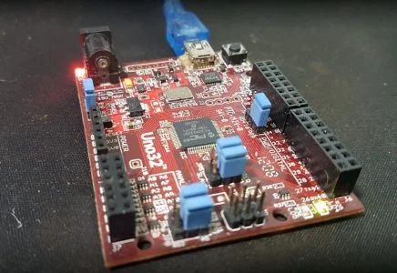
Apesar do falso cognato e verossimilhança, essa placa não é um Arduino. Apesar de parecer algo novo, também não é; aliás, é uma placa "antiga" e descontinuada, da qual escrevi a respeito há muito tempo. Então, por qual razão escrever novamente sobre essa placa? Bem, se você encontrar para comprar, compre. E explico o porque, mostrando a Uno32 chipkit no VS Code.
Características da placa
Na época havia duas IDEs que a suportavam, mas já adianto: Não usaria a MPlab; no máximo, a MPIDE. O MPlab é horrível, pesado, feio, o compilador free é limitado, tudo é instalado à parte, mexe em configurações do sistema (como regras do udev), etc. Mas, caríssimo leitor, hoje essa placa está no PlatformIO, linda e fácil de usar, bastando criar um novo projeto com ela usando o framework do Arduino!
Como os links originais não estão mais disponíveis, e provavelmente essas informações se perderão em breve, vou registrá-las aqui para perpetuá-las.
Processador
Não é uma microcontroladora de 8bits; supreenda-se! Temos aqui um PIC32MX320F128H com as seguintes características:
- 80MHz
- 32bits
- MIPS M4K
- Montes de interrupções
- 128KB de memória de programa
- 32KB de SRAM
- 2 SPI
- 2 I2C
- 16 ADC de 10 bits com 1 Mega de amostragens por segundo
- Até 53 pinos de I/O
- 64 pinos
Características da placa
- Compatível com códigos do Arduino
- Formato do Arduino UNO
- Compatível com shields Arduino
- Nível lógico 3v3
- 42 GPIO disponíveis
- 2 LEDs de uso geral
- Conexão mini-USB
- 75mA de consumo
- Tensão de entrada de 7V à 15V, marcada na placa
- 18mA por pino
Pinout
Peguei a placa no manual de referência, que encontrei em outro link. A disposição é essa:


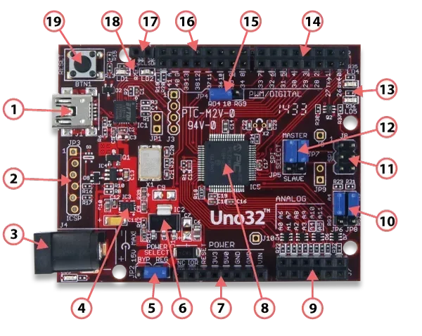
- 1 - Conector USB para programação e alimentação
- 2 - Conector do debugger
- 3 - Alimentação externa
- 4 - Regulador 3v3
- 5 - Bypass do regulador de tensão para alimentação externa
- 6 - regulador 5V
- 7 - alimentação para shields
- 8 - MCU
- 9 - ADC
- 10 - muda entre ADC e I2C nos pinos 9 e 11 ou A4 e A5, para SDA e SCL, respectivamente
- 11 - SPI
- 12 - Seletor de SPI master/slave
- 13 - LEDs do usuário, nos pinos 13 e 43
- 14 - GPIO digital
- 15 - Jumper para trocar o pino 5 (D10) de PWM para SPI.
- 16 - Conector digital
- 17 - I2C
- 18 - LEDs de comunicação
- 19 - Reset
Faltaram detalhes, mas não vou traduzir tudo porque tenho preguiça. Opcionalmente deixo o texto original:
1. USB Connector for USB Serial Converter
This connects to a USB port on the PC to provide the communications port for the MPIDE to talk to
the Uno32 board. This can also be used to power the Uno32 board when connected to the PC.

2. JP3 – Microchip Debug Tool Connector
This connector is used to connect Microchip programmer/debugger tools, such as the PICkit™3. This
allows the Uno32 board to be used as a traditional microcontroller development board using the
Microchip MPLAB® IDE.

3. J4 – External Power Connector
This is a 5.5mm x 2.1mm barrel connector used to power the Uno32 board from an external power supply.
It is wired with the center terminal as the positive supply voltage. The power supply voltage must be
in the range 7V to 15V.

4. Power Supply – 3.3V Regulator
Voltage regulator for the 3.3V power supply. This power supply can provide up to 500mA of current.

5. JP2 – Power Select Jumper
This jumper is used to route power from the external power connector through the on-board 5V voltage
regulator or to bypass the 5V regulator. The REG position routes power through the 5V regulator.
The BYP position bypasses the on-board 5V regulator. With this jumper in the BYP position the maximum
input voltage that can be applied at the external power connector is 6V.

6. Power Supply – 5V Regulator
This on-board 5V voltage regulator regulates the input voltage applied at the external power connector
to 5V. This is used to power the 3.3V regulator and to provide 5V power to expansion shields. This
regulator can provide up to 800mA of current.

7. J2 – Shield Power Connector
This connector provides power to I/O expansion shields connected to the board.

8. PIC32 Microcontroller
The PIC32MX320F128H microcontroller is the main processor for the board.

9. J7 – Analog Signal Connector
This connector provides access to analog/digital I/O pins on the microcontroller.

10. JP6/JP7 – A4/A5 Signal Select Jumpers
These jumpers are used to switch pins 9 and 11 on connector J7 between analog inputs A4 and A5 or the
I²C signals SDA and SCL.

11. J8 – SPI Signal Connector
This connector provides alternative access to the SPI signals. This is used by some shields for access
to the SPI bus.

12. JP5/JP7 – SPI Master/Slave Select Jumpers
These jumpers are used to switch the SPI signals for use of the Uno32 board as an SPI master device or
as an SPI slave device. Both jumpers should be switched together. Place the shorting blocks in the
MASTER position for master operation and in the SLAVE position for slave operation. Normally, these
jumpers are in the MASTER position.

13. User LEDs
Two LEDs connected to digital signal pins 13 and 43.

14. J6 – Digital Signal Connector
This connector provides access to digital I/O pins on the microcontroller.

15. JP4 – Pin 10 Signal Select Jumprt
This jumper is used to switch connector J5 pin 5 (digital signal 10) between pulse width modulator
(PWM) operation and SPI operation. The jumper is placed in the RD4 position for PWM output and in the
RG9 position for SPI slave operation. The shorting block on this jumper will normally be in the RD4
position. The only time it normally needs to be in the RG9 is when using the Uno32 board as an SPI
slave device.

16. J5 – Digital Signal Connector
This connector provides access to digital I/O pins on the microcontroller.

17. J11 - I²C
Dedicated I²C signals. These pins are independent of the setting of jumpers JP6 and JP8. However, if
JP6 and JP8 are in the RG3 and RG2 positions, the I²C signals will be tied to pins A4 and A5 on J7.

18. Communications Status LEDs
These LEDs indicate activity on the USB serial interface.

19. Reset Button
This button can be used to reset the microcontroller, restarting operation from the boot loader.
A documentação completa está em um pseudo PDF que disponibilizo nesse repositório.
Os pinos de IO são tolerantes a sinais 5V, mas o nível lógico é 3v3.
A tabela de pinout pelo pino lógico:
| chipKIT Pin # | Connector Pin # | PIC32 Pin # | PIC32 Signal | Notes |
|---|---|---|---|---|
| 0 | J6-01 | 34 | U1RX/SDI1/RF2 | |
| 1 | J6-03 | 33 | U1TX/SDO1/RF3 | |
| 2 | J6-05 | 42 | IC1/RTCC/INT1/RD8 | |
| 3 | J6-07 | 46 | OC1/RD0 | |
| 4 | J6-09 | 59 | RF1 | |
| 5 | J6-11 | 49 | OC2/RD1 | |
| 6 | J6-13 | 50 | OC3/RD2 | |
| 7 | J6-15 | 43 | IC2/U1CTS/INT2/RD9 | |
| 8 | J5-01 | 44 | IC3/PMCS2/PMA15/INT3/RD10 | |
| 9 | J5-03 | 51 | OC4/RD3 | |
| 10 | J5-05 | 52 | PMWR/OC5/IC5/CN13/RD4 | Selected by JP4, also on J8-6 |
| 11 | J5-07 | 6 | SDO2/PMA3/CN10/RG8 | Selected by JP5, also on J8-1 |
| 12 | J5-09 | 5 | SDI2/PMA5/CN8/RG7 | Selected by JP7, also on J8-4 |
| 13 | J5-11 | 4 | SCK2/PMA5/CN8/RG6 | Also on J8-3, User LED LD4 |
| 14/A0 | J7-01 | 14 | C2IN-/AN2/SS1/CN4/RB2 | |
| 15/A1 | J7-03 | 12 | C1IN-/AN4/CN6/RB4 | |
| 16/A2 | J7-05 | 21 | U2CTS/C1OUT/AN8/RB8 | |
| 17/A3 | J7-07 | 23 | TMS/CVREFOUT/PMA13/AN10/RB10 | |
| 18/A4 | J7-09 | 27 | TCK/PMA11/AN12/RB12 | Selected by JP6 |
| 19/A5 | J7-11 | 29 | PMALH/PMA1/U2RTS/AN14/RB14 | Selected by JP8 |
| 20/A6 | J7-02 | 13 | C2IN+/AN3/CN5/RB3 | |
| 21/A7 | J7-03 | 11 | C1IN+/AN5/CN7/RB5 | |
| 22/A8 | J7-06 | 22 | PMA7/C2OUT/AN9/RB9 | |
| 23/A9 | J7-08 | 24 | TDO/PMA12/AN11/RB11 | |
| 24/A10 | J7-10 | 28 | TDI/PMA10/AN13/RB13 | |
| 25/A11 | J7-12 | 30 | PMALL/PMA0/AN15/OCFB/CN12/RB15 | |
| 26 | J6-02 | 60 | PMD0/RE0 | |
| 27 | J6-04 | 61 | PMD1/RE1 | |
| 28 | J6-06 | 62 | PMD2/RE2 | |
| 29 | J6-08 | 63 | PMD3/RE3 | |
| 30 | J6-10 | 64 | PMD4/RE4 | |
| 31 | J6-12 | 1 | PMD5/RE5 | |
| 32 | J6-14 | 2 | PMD6/RE6 | |
| 33 | J6-16 | 3 | PMD7/RE7 | |
| 34 | J5-02 | 53 | PMRD/CN14/RD5 | |
| 35 | J5-04 | 45 | IC4/PMCS1/PMA14/INT4/RD11 | |
| 36 | J5-06 | 54 | CN15/RD6 | |
| 37 | J5-08 | 55 | CN16/RD7 | |
| 38 | J5-10 | 35 | U1RTS/BCLK1/SCK1/INT0/RF6 | |
| 39 | J5-12 | 31 | PMA9/U2RX/SDA2/CN17/RF4 | |
| 40 | J5-14 | 32 | PMA8/U2TX/SCL2/CN18/RF5 | |
| 41 | J5-16 | 15 | PGC1/AN1/VREF-/CVREF-/CN3/RB1 | |
| 42 | J5-15 | 16 | PGED1/PMA6/AN0/VREF+/CVREF+/CN2/RB0 | |
| 43 | N/A | 58 | RF0 | User LED LD5 |
| 44 | J5-05 | 8 | PMA2/SS2/CN11/RG9 | Selected by JP4, also on J8-6 |
| 45 | J11-1, J7-09 | 36 | SDA1/RG3 | J7-09 selected by JP6 |
| 46 | J11-2, J7-11 | 37 | SCL1/RG2 | J7-11 selected by JP8 |
E a tabela de pinout pelo shield:
| Connector Pin # | chipKIT Pin # | PIC32 Pin # | PIC32 Signal | Notes |
|---|---|---|---|---|
| J5-01 | 8 | 44 | IC3/PMCS2/PMA15/INT3/RD10 | |
| J5-02 | 34 | 53 | PMRD/CN14/RD5 | |
| J5-03 | 9 | 51 | OC4/RD3 | |
| J5-04 | 35 | 45 | IC4/PMCS1/PMA14/INT4/RD11 | |
| J5-05 | 10 or 44 | 52 or 8 | PMWR/OC5/IC5/CN13/RD4 or SS2/PMA2/CN11/RG9 | Selected by JP4, also on J8-6 |
| J5-06 | 36 | 54 | CN15/RD6 | |
| J5-07 | 11 or 12 | 6 or 5 | SDO2/PMA3/CN10/RG8 or SDI2/PMA5/CN8/RG7 | Selected by JP5, also on J8-1 |
| J5-08 | 37 | 55 | CN16/RD7 | |
| J5-09 | 12 or 11 | 5 or 6 | SDI2/PMA5/CN8/RG7 or SDO2/PMA3/CN10/RG8 | Selected by JP7, also on J8-4 |
| J5-10 | 38 | 35 | U1RTS/BCLK1/SCK1/INT0/RF6 | |
| J5-11 | 13 | 4 | SCK2/PMA5/CN8/RG6 | Also on J8-3, user LED LD4 |
| J5-12 | 39 | 31 | PMA9/U2RX/SDA2/CN17/RF4 | |
| J5-13 | GND | |||
| J5-14 | 40 | 32 | PMA8/U2TX/SCL2/CN18/RF5 | |
| J5-15 | 42 | 16 | PGED1/PMA6/AN0/VREF+/CVREF+/CN2/RB0 | |
| J5-16 | 41 | 15 | PGC1/AN1/VREF-/CVREF-/CN3/RB1 | |
| J6-01 | 0 | 34 | U1RX/SDI1/RF2 | |
| J6-02 | 26 | 60 | PMD0/RE0 | |
| J6-03 | 1 | 33 | U1TX/SDO1/RF3 | |
| J6-04 | 27 | 61 | PMD1/RE1 | |
| J6-05 | 2 | 42 | IC1/RTCC/INT1/RD8 | |
| J6-06 | 28 | 62 | PMD2/RE2 | |
| J6-07 | 3 | 46 | OC1/RD0 | |
| J6-09 | 4 | 59 | RF1 | |
| J6-10 | 30 | 64 | PMD4/RE4 | |
| J6-11 | 5 | 49 | OC2/RD1 | |
| J6-12 | 31 | 1 | PMD5/RE5 | |
| J6-13 | 6 | 50 | OC3/RD2 | |
| J6-14 | 32 | 2 | PMD6/RE6 | |
| J6-15 | 7 | 43 | IC2/U1CTS/INT2/RD9 | |
| J6-16 | 33 | 3 | PMD7/RE7 | |
| J7-01 | A00/14 | 14 | C2IN-/AN2/SS1/CN4/RB2 | |
| J7-02 | A06/20 | 13 | C2IN+/AN3/CN5/RB3 | |
| J7-03 | A01/15 | 12 | C1IN-/AN4/CN6/RB4 | |
| J7-03 | A07/21 | 11 | C1IN+/AN5/CN7/RB5 | |
| J7-05 | A02/16 | 21 | U2CTS/C1OUT/AN8/RB8 | |
| J7-06 | A08/22 | 22 | PMA7/C2OUT/AN9/RB9 | |
| J7-07 | A03/17 | 23 | TMS/CVREFOUT/PMA13/AN10/RB10 | |
| J7-08 | A09/23 | 24 | TDO/PMA12/AN11/RB11 | |
| J7-09 | A04/18 or 45 | 27 or 36 | TCK/PMA11/AN12/RB12 or SDA1/RG3 | Selected by JP6 |
| J7-10 | A10/24 | 28 | TDI/PMA10/AN13/RB13 | |
| J7-11 | A05/19 or 46 | 29 or 37 | PMALH/PMA1/U2RTS/AN14/RB14 or SCL1/RG2 | Selected by JP8 |
| J7-12 | A11/25 | 30 | PMALL/PMA0/AN15/OCFB/CN12/RB15 | |
| J11-1 | 45 | 36 | SDA1/RG3 | |
| J11-2 | 46 | 37 | SCL1/RG2 |
Uno32 Chipkit no VS Code
Baixe o VS Code para seu sistema nesse link. Depois de instalado, instale o plugin PlatformIO. Então crie um projeto e escolha Uno32 Chipkit. Daí basta usar como Arduino. Veja o vídeo em nosso canal através desse link.
Aproveito para sugerir a inscrição em nosso canal DobitaobyteBrasil no Youtube para prestígio do blog!
Até a próxima!
Revisão: Ricardo Amaral de Andrade
Inscreva-se no nosso canal Manual do Maker no YouTube.
Também estamos no Instagram.


Djames Suhanko
Autor do blog "Do bit Ao Byte / Manual do Maker".
Viciado em embarcados desde 2006.
LinuxUser 158.760, desde 1997.