


Manual
do
Maker
.
com
Pulseira com ESP32


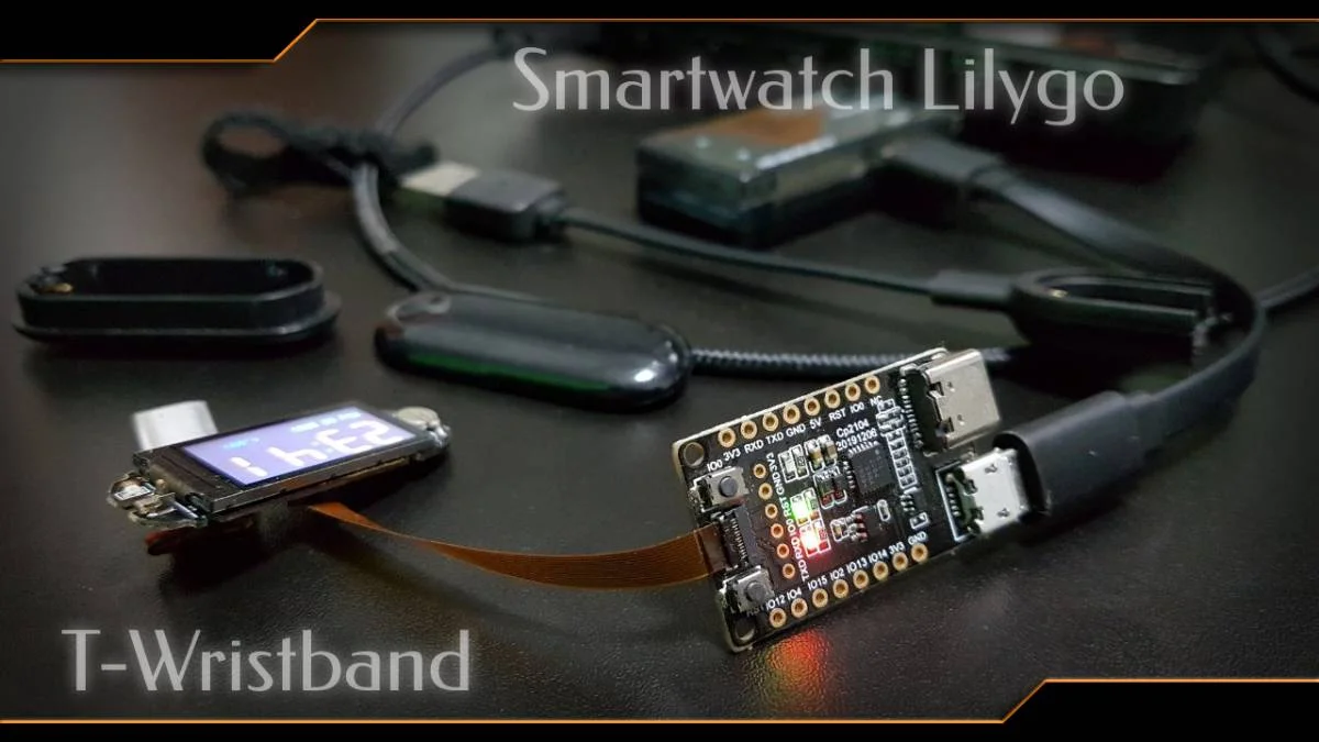
A imagem de destaque é a T-Wristband na placa de gravação. Essa pulseira com esp32 não é exatamente uma novidade, já escrevi sobre ele há algum tempo, mas na época o repositório padrão sugerido pelo fabricante não colocava o relógio pra funcionar adequadamente, provavelmente pelas variações de versões das bibliotecas. Agora está fácil e vou aproveitar pra programar algo diferente. Acompanhe o artigo!
Smartwatch ou pulseira com esp32 com ESP32?
Chamá-lo apenas de "pulseira" é subestimar o produto. Ele possui giroscópio, acelerômetro e magnetômetro funcionais, além de um RTC para a data/hora. Também mostra a tensão, além do (óbvio) display e sensor de toque capacitivo. É um espetáculo de hardware, extremamente compacto. Sua bateria é de 80mAh, daí você pode pensar: "Um ESP32 rodando com WiFi e bluetooth com uma bateria de 80mAh?" - mas calma. Deixando-o absolutamente em deep sleep, sua bateria dura quase 27 horas. Considerando que vamos utilizá-lo algumas vezes ao dia, sua carga é suficiente para 24 horas, mas se precisar de um uso mais intenso, deve dar tempo de chegar a algum lugar que tenha uma porta USB para carregá-lo. Vale citar a série sobre os modos de sleep do ESP32, onde escrevi 4 ou 5 artigos. Em deep sleep o consumo é de aproximadamente 3mA.
Setup inicial
A única parte que dá trabalho é o setup inicial, já que não basta instalar uma biblioteca. Então, vamos fazer de uma maneira bem simples.
Na IDE do Arduino, selecione a placa ESP32 Dev Module. Se ainda não tem o repositório para ESP32 na sua IDE, vá em Arquivos > Preferências e adicione essa URL no Board Manager:
https://dl.espressif.com/dl/package_esp32_index.json
Se já tiver alguma, basta separar com vírgula.
Estou usando a IDE 2.0, que ainda é beta, mas funciona bem. No vídeo dá pra ver os passos nessa nova IDE.
Feito isso, vá em Boards Manager (é o primeiro ícone da esquerda) e digite ESP32. Instale o suporte.


Repositório oficial da Lilygo T-Wristband
Agora baixe o arquivo zip ou clone o repositório que dará suporte a todo o hardware da placa. Copie tudo que está dentro do diretório libdeps para o diretório Arduino/libraries. Fiz um fork do repositório para garantir uma versão funcional permanente, caso esteja se guiando por esse artigo em qualquer momento de sua vida.
Abra um dos exemplos e compile para ver que tipo de erros pode dar. Obtive alguns erros compilando no Linux, no vídeo mostro como resolvê-los.
Assim que conseguir compilar sem problemas, basta fazer o upload. A conexão da placa de desenvolvimento é simples, só encaixar o flat cable no ESP32 e fechar o slot. Também mostro no vídeo.
Precisa desmontar toda a vez que for gravar?
Desmontar algumas vezes pode até ser legal, mas imagine estar definindo um firmware para ela, removendo bugs até chegar no "estado-da-arte". Seria um incômodo, certamente. Porém, basta gravar um firmware com suporte a OTA e considerando que não cometerá um erro que faça o dispositivo ficar reiniciando, ficará fácil gravar um novo firmware! E se cometer alguma falha grave no desenvolvimento, sem problemas também; basta desmontar e conectar o dispositivo à placa de gravação.
Projeto: Trocador de slides
Uma aplicação interessante seria um trocador de slides. Imagine estar dando uma palestra; Deixe o laptop como hot spot e tire o ESP32 de deep sleep; 1 toque adianta o slide, 2 toque volta o slide. Com isso, não precisamos sair de foco para clicar em slides, nem pedir para alguém avançar para o próximo. Segurando o touch por 3 segundos, entraremos em deep sleep novamente. Bora pro código.
Lembre-se: Siga o processo descrito e abra um sketch de exemplo, ele trará todas as dependências sem precisar se preocupar com mais nada. Salve esse sketch com outro nome e substitua o código por esse:
#include <pcf8563.h>
#include <TFT_eSPI.h> // Graphics and font library for ST7735 driver chip
#include <SPI.h>
#include <Wire.h>
#include <WiFi.h>
#include "sensor.h"
#include "esp_adc_cal.h"
#include "ttgo.h"
#include "charge.h"
#include "credentials.h"

#define TP_PIN_PIN          33
#define I2C_SDA_PIN         21
#define I2C_SCL_PIN         22
#define IMU_INT_PIN         38
#define RTC_INT_PIN         34
#define BATT_ADC_PIN        35
#define VBUS_PIN            36
#define TP_PWR_PIN          25
#define LED_PIN             4
#define CHARGE_PIN          32

extern MPU9250 IMU;

TFT_eSPI tft = TFT_eSPI();  // Invoke library, pins defined in User_Setup.h
PCF8563_Class rtc;

char buff[256];
bool rtcIrq = false;
bool initial = 1;
bool otaStart = false;

uint8_t func_select = 0;
uint8_t omm = 99;
uint8_t xcolon = 0;
uint32_t targetTime = 0;       // for next 1 second timeout
uint32_t colour = 0;
int vref = 1100;

bool doit    = true;
bool pressed = false;
uint32_t pressedTime = 0;
bool charge_indication = false;
unsigned long int pressed_time = 0;
uint8_t count = 0;
uint8_t hh, mm, ss ;

void go_down(){
        tft.setTextColor(TFT_GREEN, TFT_BLACK);
        tft.setTextDatum(MC_DATUM);
        tft.drawString("Press again to wake up",  tft.width() / 2, tft.height() / 2 );
        IMU.setSleepEnabled(true);
        Serial.println("Go to Sleep");
        delay(3000);
        tft.writecommand(ST7735_SLPIN);
        tft.writecommand(ST7735_DISPOFF);
        esp_sleep_enable_ext1_wakeup(GPIO_SEL_33, ESP_EXT1_WAKEUP_ANY_HIGH);
        esp_deep_sleep_start();
}

void touchMonitor(void *pvParameters){
    while (true){
        pressed_time = millis();
        uint8_t tp_state = digitalRead(TP_PIN_PIN);
        doit = tp_state > 0 ? true : false;
        if (doit){
          while (digitalRead(TP_PIN_PIN)){
            vTaskDelay(pdMS_TO_TICKS(10));
          }

          if ((millis()-pressed_time) < 1000){
            Serial.println("MENOR QUE 1s");
          }
          else if ((millis()-pressed_time) > 1000 && (millis()-pressed_time) < 3000) {
            Serial.println("MAIOR QUE 1s");
          }
          else if ((millis()-pressed_time) > 3000){
            go_down();
          }
        }
        vTaskDelay(pdMS_TO_TICKS(10));
    }
}

void shortTouchMonitor(void *pvParameters){
    unsigned long int taps = millis();
    int time_limit = 3000;
    while (true){

      //contador
      if (digitalRead(TP_PIN_PIN) && (millis()-taps) < time_limit){
        count += 1;
        vTaskDelay(pdMS_TO_TICKS(200));
      }

      //validador: se for 1 e não tiver mais toque e já deu timeout...
      if (count == 1 && !digitalRead(TP_PIN_PIN) && (millis()-taps) > time_limit){
        Serial.println("Next");
        taps = millis();
        count = 0;
      }
      //senão, se 2 e não tiver mais toque e já deu timeout...
      else if (count == 2 && !digitalRead(TP_PIN_PIN) && (millis()-taps) > time_limit){
        Serial.println("Previous");
        taps = millis();
        count = 0;
      }
      //se não teve toque e excedeu o tempo...
      else if ((millis()-taps) > time_limit && count == 0){
        taps = millis();
        vTaskDelay(pdMS_TO_TICKS(200));
      }
    }
    vTaskDelay(pdMS_TO_TICKS(10));
}

void scanI2Cdevice(void)
{
    uint8_t err, addr;
    int nDevices = 0;
    for (addr = 1; addr < 127; addr++) {
        Wire.beginTransmission(addr);
        err = Wire.endTransmission();
        if (err == 0) {
            Serial.print("I2C device found at address 0x");
            if (addr < 16)
                Serial.print("0");
            Serial.print(addr, HEX);
            Serial.println(" !");
            nDevices++;
        } else if (err == 4) {
            Serial.print("Unknow error at address 0x");
            if (addr < 16)
                Serial.print("0");
            Serial.println(addr, HEX);
        }
    }
    if (nDevices == 0)
        Serial.println("No I2C devices found\n");
    else
        Serial.println("Done\n");
}

void factoryTest()
{
    scanI2Cdevice();
    delay(2000);

    tft.fillScreen(TFT_BLACK);
    tft.drawString("RTC Interrupt self test", 0, 0);

    int yy = 2021, mm = 5, dd = 27, h = 3, m = 15, s = 0;
    rtc.begin(Wire);
    rtc.setDateTime(yy, mm, dd, h, m, s);
    delay(500);
    RTC_Date dt = rtc.getDateTime();

    if (dt.year != yy || dt.month != mm || dt.day != dd || dt.hour != h || dt.minute != m) {
        tft.setTextColor(TFT_RED, TFT_BLACK);
        tft.fillScreen(TFT_BLACK);
        tft.drawString("Write DateTime FAIL", 0, 0);
    } else {
        tft.setTextColor(TFT_GREEN, TFT_BLACK);
        tft.fillScreen(TFT_BLACK);
        tft.drawString("Write DateTime PASS", 0, 0);
    }
}

void setupADC()
{
    esp_adc_cal_characteristics_t adc_chars;
    esp_adc_cal_value_t val_type = esp_adc_cal_characterize((adc_unit_t)ADC_UNIT_1, (adc_atten_t)ADC1_CHANNEL_6, (adc_bits_width_t)ADC_WIDTH_BIT_12, 1100, &adc_chars);
    //Check type of calibration value used to characterize ADC
    if (val_type == ESP_ADC_CAL_VAL_EFUSE_VREF) {
        Serial.printf("eFuse Vref:%u mV", adc_chars.vref);
        vref = adc_chars.vref;
    } else if (val_type == ESP_ADC_CAL_VAL_EFUSE_TP) {
        Serial.printf("Two Point --> coeff_a:%umV coeff_b:%umV\n", adc_chars.coeff_a, adc_chars.coeff_b);
    } else {
        Serial.println("Default Vref: 1100mV");
    }
}

void setupRTC()
{
    rtc.begin(Wire);
    //Check if the RTC clock matches, if not, use compile time
    rtc.check();

    RTC_Date datetime = rtc.getDateTime();
    hh = datetime.hour;
    mm = datetime.minute;
    ss = datetime.second;
}

void setupWiFi(){
    WiFi.begin(SSID,PASSWD);
    for (uint8_t i=0;i<10;i++){
      Serial.print(".");
      delay(200);
      while (WiFi.status() != WL_CONNECTED){
        delay(100);
        Serial.print(".");
      }
      Serial.println(WiFi.localIP());
    }
}

void setup(void)
{
    Serial.begin(115200);

    tft.init();
    tft.setRotation(1);
    tft.setSwapBytes(true);
    tft.pushImage(0, 0,  160, 80, ttgo);

    Wire.begin(I2C_SDA_PIN, I2C_SCL_PIN);
    Wire.setClock(400000);

    //factoryTest(); //após ajustar a hora, comentar essa função

    setupRTC();

    setupMPU9250();

    setupADC();

    setupWiFi();


    tft.fillScreen(TFT_BLACK);

    tft.setTextColor(TFT_YELLOW, TFT_BLACK); // Note: the new fonts do not draw the background colour

    targetTime = millis() + 1000;

    pinMode(TP_PIN_PIN, INPUT);
    //! Must be set to pull-up output mode in order to wake up in deep sleep mode
    pinMode(TP_PWR_PIN, PULLUP);
    digitalWrite(TP_PWR_PIN, HIGH);

    pinMode(LED_PIN, OUTPUT);

    pinMode(CHARGE_PIN, INPUT_PULLUP);
    attachInterrupt(CHARGE_PIN, [] {
        charge_indication = true;
    }, CHANGE);

    if (digitalRead(CHARGE_PIN) == LOW) {
        charge_indication = true;
    }

    //xTaskCreatePinnedToCore(touchMonitor,"touchMonitor", 10000, NULL, 1, NULL,0);
    xTaskCreatePinnedToCore(shortTouchMonitor,"shortTtouchMonitor", 10000, NULL, 1, NULL,0);
}

String getVoltage()
{
    uint16_t v = analogRead(BATT_ADC_PIN);
    float battery_voltage = ((float)v / 4095.0) * 2.0 * 3.3 * (vref / 1000.0);
    return String(battery_voltage) + "V";
}

void RTC_Show()
{
    if (targetTime < millis()) {
        RTC_Date datetime = rtc.getDateTime();

        hh = datetime.hour;
        mm = datetime.minute;
        ss = datetime.second;
        // Serial.printf("hh:%d mm:%d ss:%d\n", hh, mm, ss);
        targetTime = millis() + 1000;
        if (ss == 0 || initial) {
            initial = 0;
            tft.setTextColor(TFT_GREEN, TFT_BLACK);
            tft.setCursor (8, 60);
            tft.print(__DATE__); // This uses the standard ADAFruit small font
        }

        tft.setTextColor(TFT_BLUE, TFT_BLACK);
        tft.drawCentreString(getVoltage(), 120, 60, 1); // Next size up font 2


        // Update digital time
        uint8_t xpos = 6;
        uint8_t ypos = 0;
        if (omm != mm) { // Only redraw every minute to minimise flicker
            // Uncomment ONE of the next 2 lines, using the ghost image demonstrates text overlay as time is drawn over it
            tft.setTextColor(0x39C4, TFT_BLACK);  // Leave a 7 segment ghost image, comment out next line!
            //tft.setTextColor(TFT_BLACK, TFT_BLACK); // Set font colour to black to wipe image
            // Font 7 is to show a pseudo 7 segment display.
            // Font 7 only contains characters [space] 0 1 2 3 4 5 6 7 8 9 0 : .
            tft.drawString("88:88", xpos, ypos, 7); // Overwrite the text to clear it
            tft.setTextColor(0xFBE0, TFT_BLACK); // Orange
            omm = mm;

            if (hh < 10) xpos += tft.drawChar('0', xpos, ypos, 7);
            xpos += tft.drawNumber(hh, xpos, ypos, 7);
            xcolon = xpos;
            xpos += tft.drawChar(':', xpos, ypos, 7);
            if (mm < 10) xpos += tft.drawChar('0', xpos, ypos, 7);
            tft.drawNumber(mm, xpos, ypos, 7);
        }

        if (ss % 2) { // Flash the colon
            tft.setTextColor(0x39C4, TFT_BLACK);
            xpos += tft.drawChar(':', xcolon, ypos, 7);
            tft.setTextColor(0xFBE0, TFT_BLACK);
        } else {
            tft.drawChar(':', xcolon, ypos, 7);
        }
    }
}

void IMU_Show()
{
    tft.setTextColor(TFT_GREEN, TFT_BLACK);
    tft.fillScreen(TFT_BLACK);
    tft.setTextDatum(TL_DATUM);
    readMPU9250();
    snprintf(buff, sizeof(buff), "--  ACC  GYR   MAG");
    tft.drawString(buff, 0, 0);
    snprintf(buff, sizeof(buff), "x %.2f  %.2f  %.2f", (int)1000 * IMU.ax, IMU.gx, IMU.mx);
    tft.drawString(buff, 0, 16);
    snprintf(buff, sizeof(buff), "y %.2f  %.2f  %.2f", (int)1000 * IMU.ay, IMU.gy, IMU.my);
    tft.drawString(buff, 0, 32);
    snprintf(buff, sizeof(buff), "z %.2f  %.2f  %.2f", (int)1000 * IMU.az, IMU.gz, IMU.mz);
    tft.drawString(buff, 0, 48);
    delay(200);
}


void loop(){
    if (charge_indication){
        charge_indication = false;
        if (digitalRead(CHARGE_PIN) == LOW){
            tft.pushImage(140, 55, 16, 16, charge);
        }
        else{
            tft.fillRect(140, 55, 16, 16, TFT_BLACK);
        }
    }


    if (digitalRead(TP_PIN_PIN) == HIGH && 3>4){
        if (!pressed){
            initial = 1;
            targetTime = millis() + 1000;
            tft.fillScreen(TFT_BLACK);
            omm = 99;
            func_select = func_select + 1 > 2 ? 0 : func_select + 1;
            digitalWrite(LED_PIN, HIGH);
            delay(100);
            digitalWrite(LED_PIN, LOW);
            pressed = true;
            pressedTime = millis();
        }
        else{
            if (millis() - pressedTime > 3000){
                tft.fillScreen(TFT_BLACK);
                tft.drawString("Not used",  20, tft.height() / 2 );
                delay(3000);
            }
        }
    }
    else{
        pressed = false;
    }

    switch (func_select) {
    case 0:
        RTC_Show();
        break;
    case 1:
        IMU_Show();
        break;
    case 2:
        tft.setTextColor(TFT_GREEN, TFT_BLACK);
        tft.setTextDatum(MC_DATUM);
        tft.drawString("Press again to wake up",  tft.width() / 2, tft.height() / 2 );
        IMU.setSleepEnabled(true);
        Serial.println("Go to Sleep");
        delay(3000);
        tft.writecommand(ST7735_SLPIN);
        tft.writecommand(ST7735_DISPOFF);
        esp_sleep_enable_ext1_wakeup(GPIO_SEL_33, ESP_EXT1_WAKEUP_ANY_HIGH);
        esp_deep_sleep_start();
        break;
    default:
        break;
    }
}
Com esse código, um toque em um intervalo de 3 segundos mostrará "Next" na serial e dois toques nesse intervalo mostrará "Previous". No vídeo mostrarei trocando slide e passo o link do repositório, agora vou dar um tapa na comunicação com o laptop para receber o comando.
Mentiria se dissesse que é um bom código; apenas joguei algumas coisas fora e incuti funções quase que sem consentimento, daria até processo se a MCU rodasse uma IA. Mas funciona para o propósito do artigo, que mostrarei no vídeo "smartwatch com esp32" ou "pulseira com esp32" em nosso canal DobitaobyteBrasil no Youtube. Aproveito para agradecer a vocês leitores que tem mostrado claramente seu apoio se inscrevendo no canal. Espero que os vídeos estejam atingindo suas expectativas. Os efeitos especiais não são fundamentais, eu sei, mas ajudam a distrair a mente enquanto pensamos tecnicamente. E convenhamos, minha dicção é uma m****. Quando não estou lendo o texto, parece que estou também, mas o conteúdo é caprichado.
Inscreva-se no nosso canal Manual do Maker no YouTube.
Também estamos no Instagram.


Djames Suhanko
Autor do blog "Do bit Ao Byte / Manual do Maker".
Viciado em embarcados desde 2006.
LinuxUser 158.760, desde 1997.